Hello, welcome to the official website of BolaiKong Technology (Wuxi) Co., Ltd.!
Hello, welcome to the official website of BolaiKong Technology (Wuxi) Co., Ltd.!


Addressing common technical and operational questions regarding valve selection, installation, and maintenance
For the above two reasons, when selecting steam traps, the drainage capacity of the steam trap must be multiplied by a safety factor.
Several factors must be considered when selecting the appropriate steam trap, but the primary factors are as follows:
During the phase transition of water, the system in which the two phases of water and water vapor coexist in equilibrium is called saturated. This saturation state exists a critical point, the temperature of this critical point becomes the critical temperature, the value of 374.15 ℃.
The pressure at the critical point is the critical pressure and has a value of 22.12 MPa.
The steam leakage rate of steam traps is categorized into load leakage rate and no-load leakage rate.
Steam leakage rate under load:
The steam leakage rate under load refers to the ratio of steam leakage volume under load to the actual condensate discharge volume during the test period.
Unloaded steam leakage rate:
The no-load steam leakage rate refers to the ratio of no-load steam leakage volume to the maximum condensate discharge volume at the corresponding pressure.
The primary function of a steam trap is to promptly discharge condensate from steam heating equipment or steam piping systems while preventing steam leakage. This enhances the efficiency of steam-using equipment and achieves energy conservation. Therefore, the key indicators for evaluating a steam trap's performance should be its drainage capacity and steam-blocking capability. Based on the definition of steam leakage rate, the magnitude of a steam trap's leakage rate comprehensively reflects the quality of its drainage and steam-blocking performance.
A steam trap is a valve that automatically removes condensate from steam lines and steam-using equipment while preventing steam leakage.
There are nine performance metrics for steam traps: shell strength, operating performance, minimum working pressure, maximum working pressure, maximum backpressure ratio, steam leakage rate, air venting capacity, discharge temperature, and discharge volume.
Due to the large contact area between the body and plug of the plug valve, significant torque is generated when rotating the plug. Surface corrosion rapidly compromises the sealing integrity of the closing mechanism and increases the torque required to operate the plug valve.
Steel and cast iron plug valves used for corrosive media shall be equipped with phenolic protective coatings and other plastic protective coatings.
The national standard GB/T 12237 "petroleum, petrochemical and related industrial steel ball valves" in the provisions of the ball valve stem should be designed to the pressure of the medium, the removal of the stem sealing packing (such as the removal of the packing gland), the valve stem will not be washed out of the valve body structure.
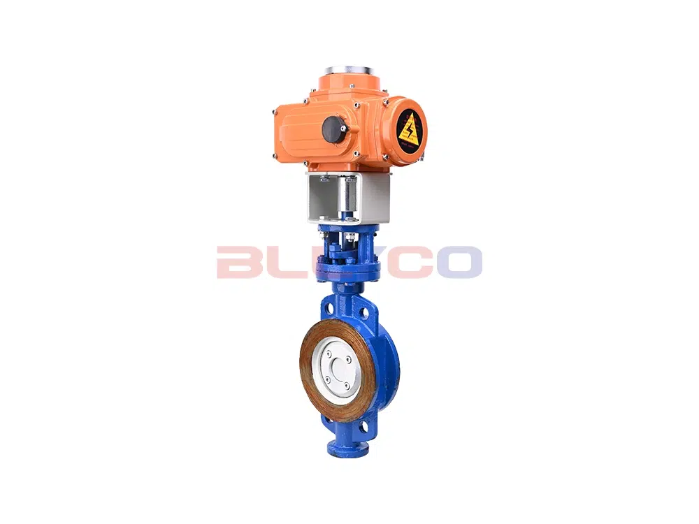
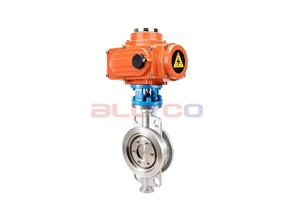
One-way sealing butterfly valve:
Unidirectional sealing butterfly valves feature a disc that faces the flow direction of the medium when closed. The medium flows in only one direction, and the valve body must display an arrow indicating the flow direction. During installation, pay attention to the direction of medium flow.
Double-sealed butterfly valve:
Bidirectional sealing butterfly valves feature a disc that can face either direction relative to the flow of the medium. Installation does not require consideration of the medium flow direction, and the valve body lacks arrows indicating flow direction. The stem of a bidirectional sealing butterfly valve experiences greater forces than that of a unidirectional sealing butterfly valve. In design, for butterfly valves of the same diameter and pressure rating, the stem diameter of a bidirectional sealing butterfly valve is larger than that of a unidirectional sealing butterfly valve.
The horizontal projection of the pivot pin axis of the swing check valve is perpendicular to the axis of the valve body's water passage and inclined at an angle to the sealing surface.
For standard globe valves, the medium flows into the valve from below the valve disc and out from above the valve disc. If the globe valve has a double valve disc, the medium flows into the valve from above the valve disc and out from below the valve disc. Globe valves with DN greater than 250 mm permit the medium to flow into the valve from above the valve disc.
When conducting performance tests on steel gate valves, care must be taken to avoid applying external forces at both ends of the valve that could affect leakage at the sealing surfaces.
The national standard GB/T 12234 "steel gate valve with bolted bonnet for oil and gas industry" stipulates that the stem nut should be loaded from the upper part of the bracket, and the upper part of the stem nut of the gate valve should be a prismatic body, a cylinder with a keyway, or a structure of equal strength connected with the handwheel. When the valve is opened, the handwheel can be removed without causing the stem and gate to fall to the closed position. If a bearing gland with threads is applied, it shall be secured by spot welding or other means.
Double-sided forced sealing for gate valves:
This means that whether at the inlet or outlet end of the medium, the gate plate and valve seat sealing surfaces remain sealed. The sealing integrity is forcibly maintained by the axial force of the valve stem. When no medium is present, the positive pressure between the sealing surfaces must not be less than the sum of the medium's static pressure and the sealing force.
Single-face forced sealing for gate valves:
This means that no seal exists between the gate plate and the valve seat sealing surface at the medium inlet end. Here, either no pressure differential exists at all, or the pressure differential is less than the sealing pressure. On the medium outlet side, the seal between the gate plate and the valve seat sealing surface is forcibly maintained by the axial force of the valve stem and the medium pressure. When no medium is present, the pressure differential across the sealing surfaces must not be less than the sealing pressure.
(1) Classified into two types based on the structure of the gate plate
(2) Classified into two types based on valve stem construction
The minimum stem diameter refers to the diameter of the portion of the stem that contacts the packing. The minimum stem diameter refers to the diameter of the stem thread relief groove.
The paint color of the handles and handwheels corresponds to the paint color of the sealing surface material, as detailed in the table below.
Valve handle and handwheel paint color:
Sealing surface material | Handle and handwheel paint colors | Sealing surface material | Handle and handwheel paint colors |
Bronze or Brass | red (color) | Cemented carbide | azure |
pasteurized alloy | yellow (color) | plastics | prune (color) |
铝 | aluminum white | Foundry Iron | ferrous |
Acid-resistant steel, stainless steel | light blue | caoutchouc | medium green |
nitriding steel | lilac | Monel alloy | navy blue |
The opening and closing directions for general valves are specified as follows: clockwise for closing and counterclockwise for opening.
The mandatory and optional markings for general-purpose valves are shown in the table below.
Valve markings:
sports event | symbolize | sports event | symbolize |
1 | Nominal Size DN (NPS) | 11 | Product standard code |
2 | Nominal pressure PN (class) | 12 | furnace number |
3 | Material designation of pressurized parts | 13 | Material designation of internal parts |
4 | Manufacturer's name or trademark | 14 | job number |
5 | Arrow for media flow direction | 15 | Lining Material Designator |
6 | Seal Ring (Gasket) Designator | 16 | Quality and test marks |
7 | Limiting temperature (°C) | 17 | Inspector's imprint |
8 | Thread code | 18 | Product Manufacturing License No. |
9 | ultimate pressure | 19 | Year and month of manufacture |
10 | Manufacturing plant number | 20 | Quality Satisfaction Level (QSL) |
Note: When the nominal pressure value cast on the valve body equals ten times the megapascal (MPa) figure and is positioned below the nominal pressure value, it is not preceded by the designation “PN”.
Marking method:
(1) Valve marking for nominal sizes greater than or equal to DN50:
(2) Marking for valves with nominal sizes less than DN50:
(3) Additional markings:
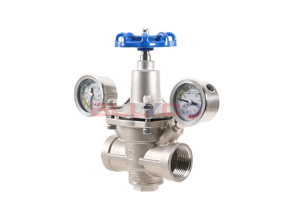
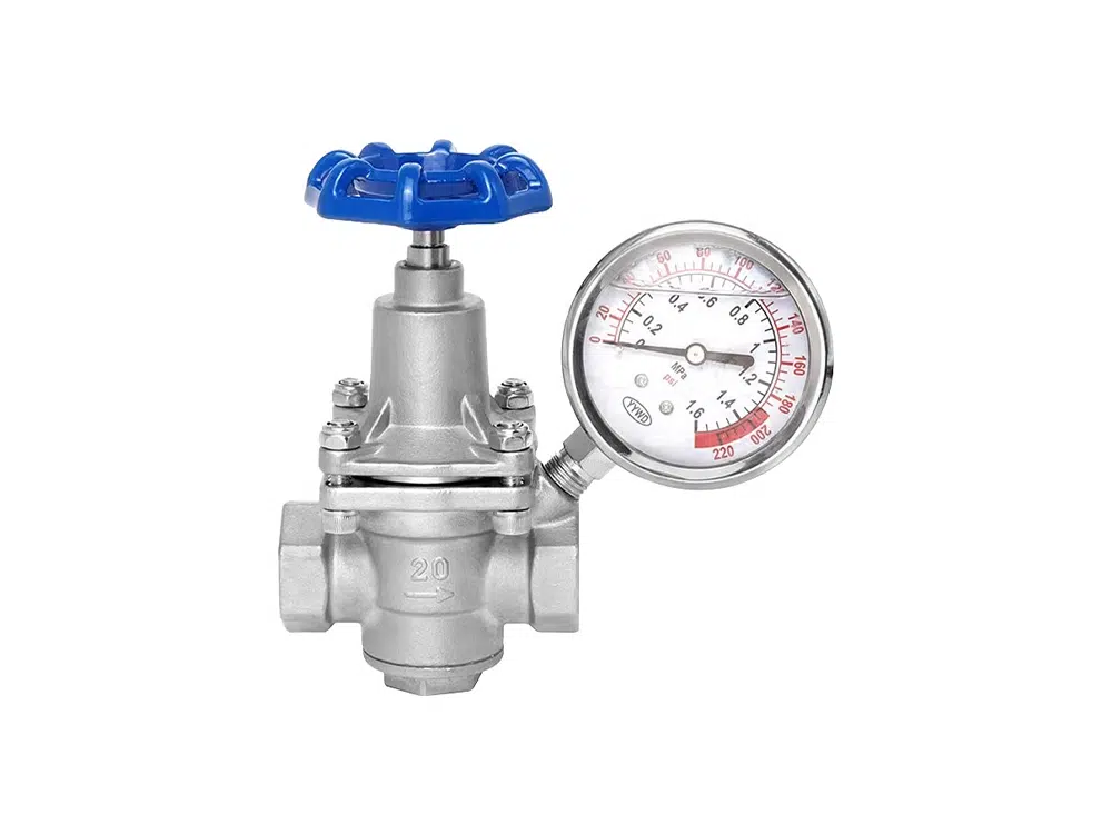
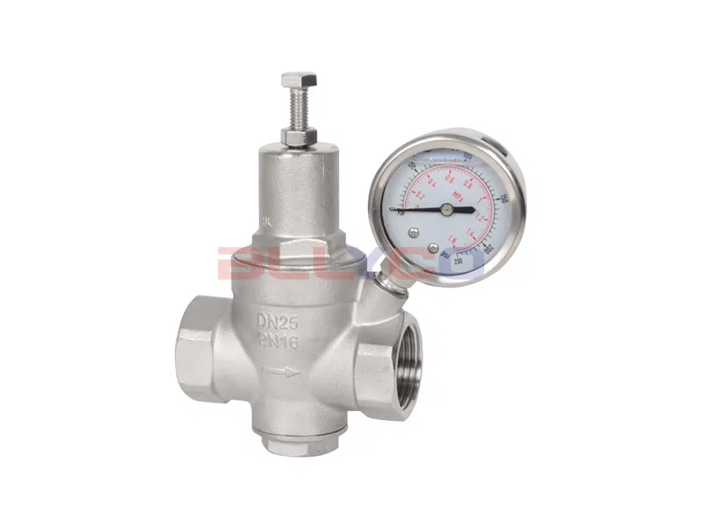
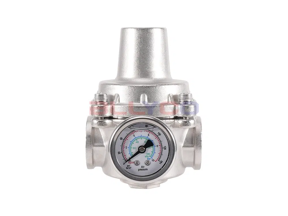
For pressure reducing valves, in addition to the 19 items specified for general valves, the markings on the valve body shall also include: date of manufacture, applicable medium, and outlet pressure.
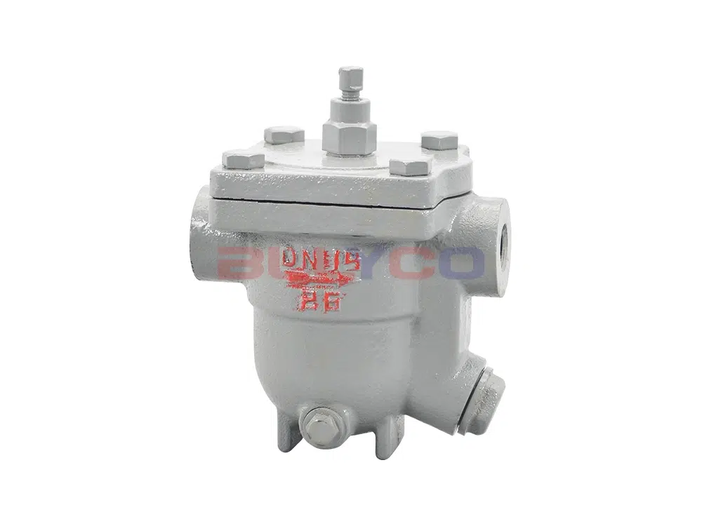
For steam trap markings, in accordance with GB/T 12250-2005, the markings may be affixed to the valve body or displayed on a nameplate.
The marking of safety valves shall comply with the provisions of GB/T 12241-2005.
Ball valves, parallel gate valves, and plug valves shall be marked in accordance with API 6D-2014.
The sealing surface material code for surfaces machined directly from the valve body is denoted by “W”. Codes for other materials are listed in the table below.
Seat sealing surface or lining material code:
Seat sealing surface or lining material | nicknames | Seat sealing surface or lining material | nicknames |
Tin-based bearing alloys (pasteurized alloys) | B | Nylon Plastic | N |
enamels | C | Boron-infiltrated steel | P |
nitriding steel | D | lead lining | Q |
fluoroplastic | F | austenitic stainless steel | R |
ceramics | G | plastics | S |
Cr13 stainless steel | H | Copper Alloy | T |
rubber lining | J | caoutchouc | X |
Monel alloy | M | Cemented carbide | Y |
Note: When the sealing surfaces of a sealing pair are made of different materials, the designation code of the softer material shall be used.
For gate, globe, and check valves, as well as ball and butterfly valves, the sealing specific pressure qMF must be less than the sealing specific pressure q, and the sealing specific pressure is less than the sealing allowable specific pressure [q] (i.e., qMF < q < [q]).
![]()
Specialized in the development and production of fluid control valves
Our leading production:ball valves, butterfly valves, gate valves, globe valves, check valves, filters, water control valves, pressure reducing valves, balancing valves, regulating valves, pneumatic valves, electric valves, and other high, medium and low pressure valves.