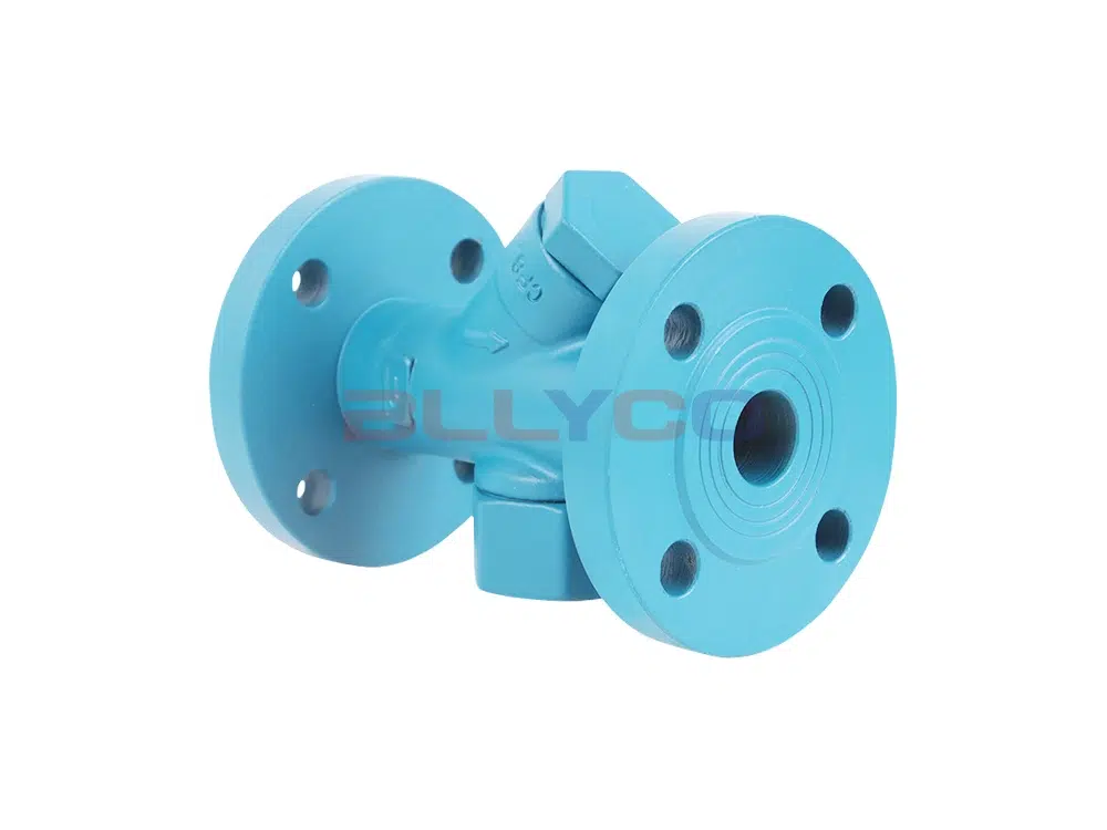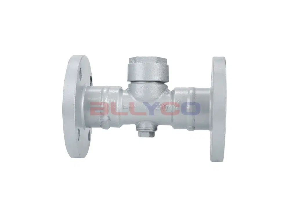
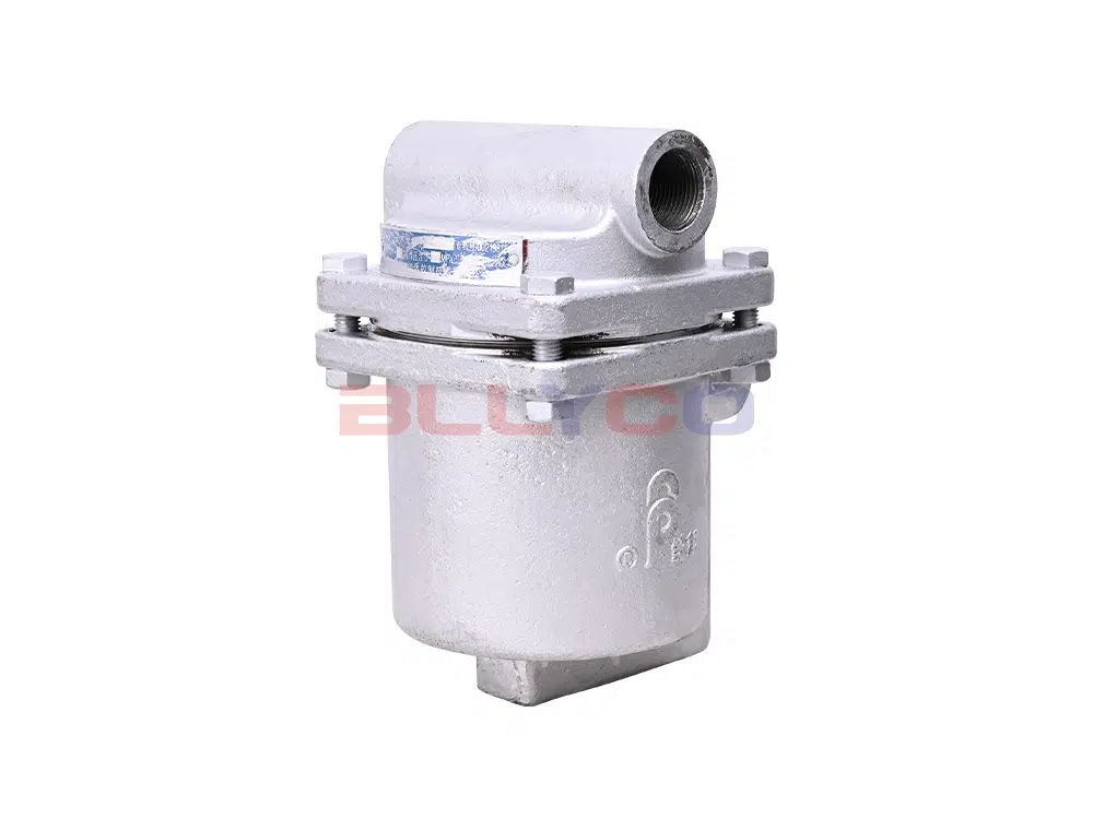
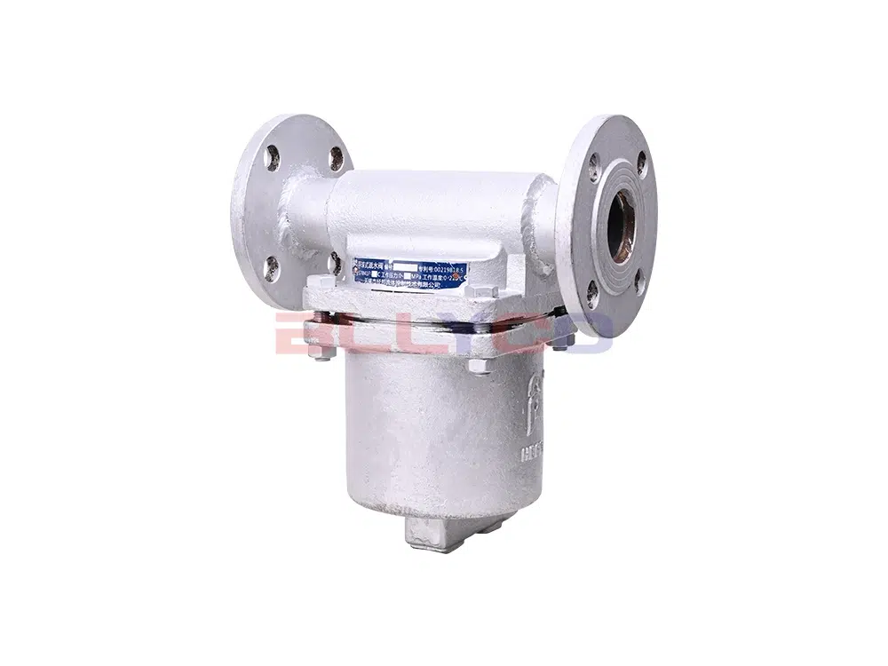
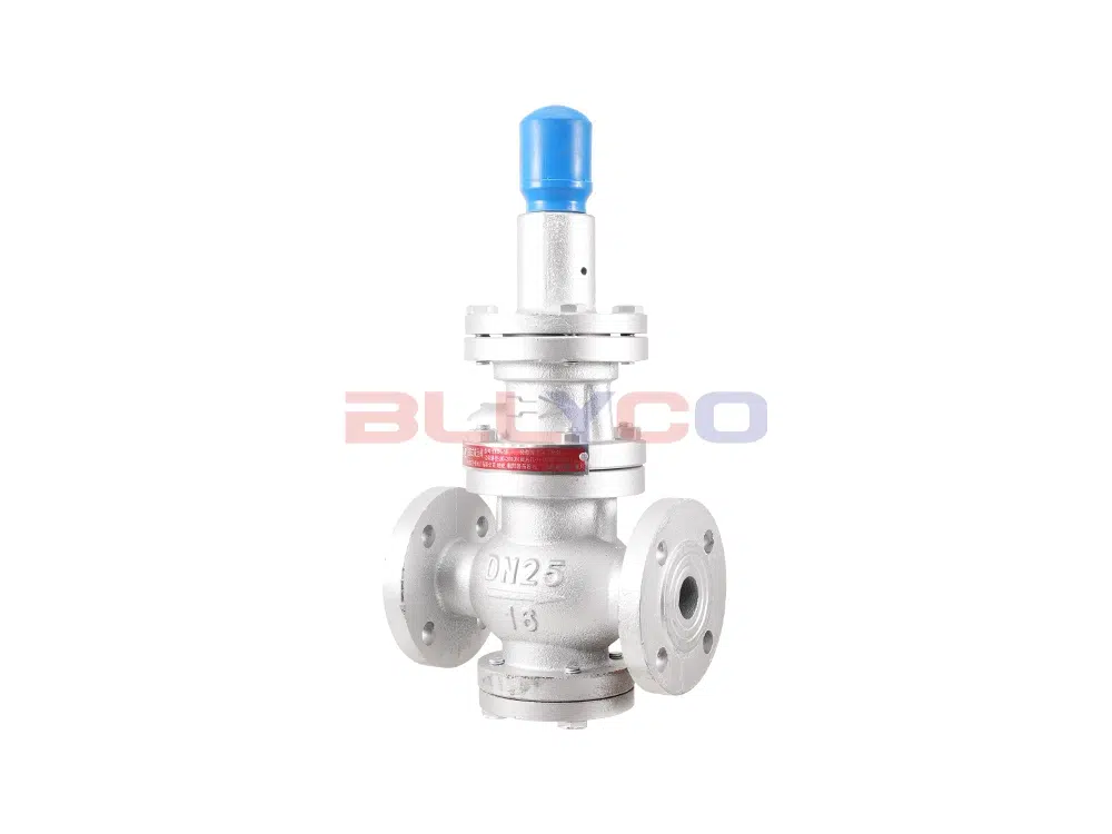
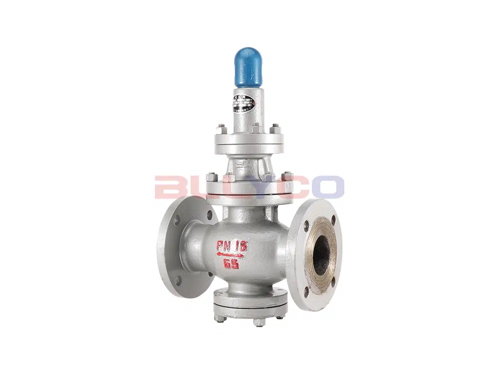
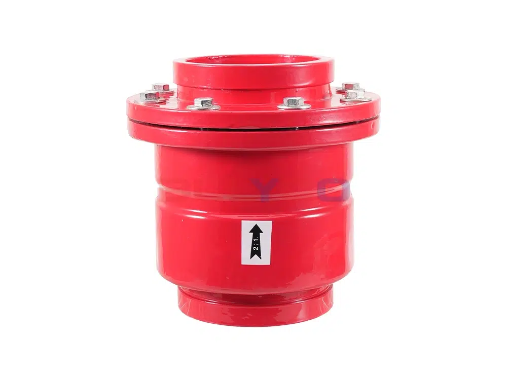
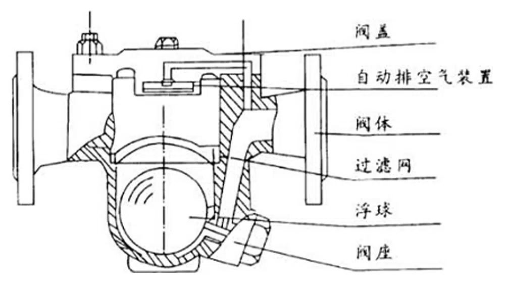
CS41H flange free float steam trap utilizes the density difference between condensate and steam to open or close the valve by changing the level of condensate so that the surface of the hollow float fits the valve seat and achieves the purpose of blocking gas and discharging water. The valve utilizes the principle of buoyancy, and the float lifts according to the amount of condensate with the change of water level, automatically adjusting the opening of the valve seat hole and continuously discharging the condensate. When the condensate stops entering, the float drops to the bottom by its own weight and closes the drain valve seat. Since the drain valve seat hole is below the condensate level, the water vapor is naturally separated and a water seal is formed, resulting in no steam leakage.
Structural Characteristics
- Highly precision ground stainless steel float, improved pressure strength and sealing performance, corrosion resistance.
- The parts of the action are floating balls, which work reliably and have a long service life.
- The ability to continuously discharge saturated condensate heating equipment without water buildup, resulting in high heat transfer efficiency.
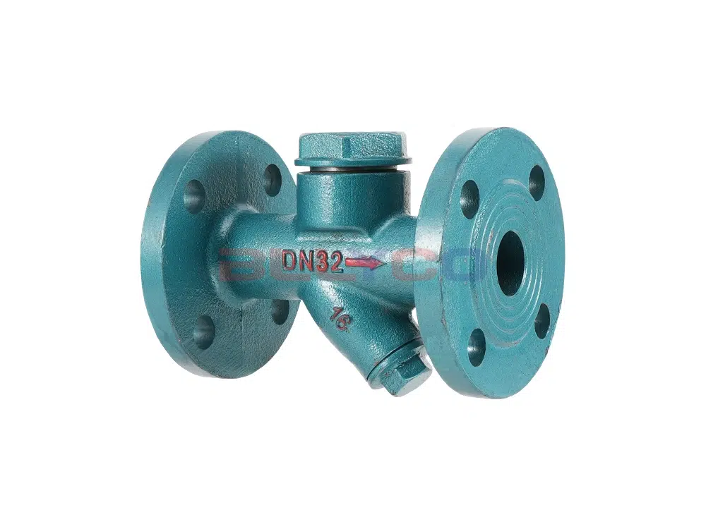
- Steam pressure changes are not affected, the float can automatically adjust the opening of the drain valve seat hole, continuous operation and stable performance.
- External manual air venting device, pneumatic quickly.
- The no-load air leakage rate is less than 0.51 TP3T.
- Maximum operating back pressure 80%.
- Subcooling <5°C.
Product Parameters
Product Model | CS41H-16C |
Valve body material | Cast Steel |
Nominal pressure | ≤1.6Mpa |
Applicable medium | Steam, Condensate |
Applicable temperature | ≤350°C |
Product Size Reference
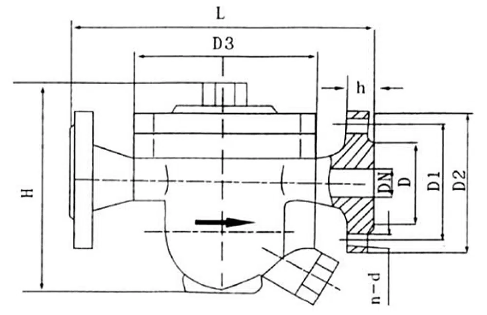
Nominal Diameter | D | D1 | D2 | D3 | H | h | L | n-d |
DN15 | 95 | Φ65 | 45 | 140 | 175 | 16 | 195±2 | 4-14 |
DN20 | 105 | Φ75 | 55 | 140 | 180 | 16 | 195±2 | 4-14 |
DN25 | 115 | Φ85 | 65 | 140 | 181 | 16 | 215±2 | 4-14 |
DN32 | 135 | Φ100 | 78 | 195 | 265 | 16 | 280±3 | 4-18 |
DN40 | 145 | Φ110 | 85 | 195 | 270 | 16 | 280±3 | 4-18 |
DN50 | 160 | Φ125 | 100 | 195 | 274 | 16 | 290±3 | 4-18 |
DN65 | 180 | Φ145 | 120 | 260 | 410 | 16 | 410±3 | 4-18 |
DN80 | 195 | Φ160 | 135 | 260 | 410 | 16 | 430±3 | 8-18 |
DN100 | 215 | Φ180 | 155 | 290 | 465 | 16 | 440±3 | 8-18 |
Continuous condensate discharge meter [unit: kilograms per hour (Kg/h)]
working pressure difference | DN15 | DN20 | DN25 | DN32 | DN40 | DN50 | DN65 | DN80 | DN100 |
0.2Mpa | 200 | 210 | 226 | 790 | 880 | 933 | 3800 | 3950 | 4980 |
0.4Mpa | 285 | 297 | 378 | 1110 | 1220 | 1300 | 5300 | 5410 | 5500 |
0.6Mpa | 380 | 395 | 498 | 1550 | 1680 | 1850 | 5200 | 6010 | 6300 |
0.8Mpa | 570 | 590 | 614 | 1950 | 2050 | 2280 | 6000 | 6220 | 6450 |
1.0 Mpa | 780 | 810 | 890 | 2300 | 2430 | 2520 | 6200 | 6400 | 6580 |
1.2Mpa | 985 | 1015 | 1150 | 2450 | 2600 | 2760 | 6450 | 6650 | 6700 |
1.6Mpa | 1120 | 1160 | 1315 | 2780 | 2880 | 2970 | 6700 | 6800 | 6950 |